What about the gravity. When an object moves, it shift around the gravitational field of itself together with. The field can be superposed like the top moves as Fig.1.1 using earth gravity. Likewise, changing relative position between two rotating disks, condition of the field could be varied by their superpose not to use earth. If unsymmetrical gravitational field be maked, an object in the field be not to hold thier position.
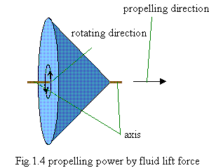
We become aware to make two disks superposition attach together and rotating. Making a gyroscope that has similar to Fig.1.4 structure, it is expected that the propelling power direction would be opposite side of Fig.1.4 because of the result is opposite between fluid hydraulic and gravitation. This conclusion is by observing Fig.1.1.
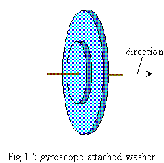
Proof wins over the argument. You can obtain a toy gyroscope at toy shop quite cheaply. Attach a washer to the center of the gyroscope and spin it at high revolutions with an electric motor (Ex. using drill attached polish nozzle). You can observe the propelling direction as per fig.1.5. This experiment is not so difficult. If you have any doubt, please try it yourself (but be aware of the risk of injury from such a high speed turning object). The gyroscope's diameter was about 5cm, weight about 80g. Putting it on the smooth surface desk as its axis setting parallel against a horizontal line because of reducing the influence of earth gravity, you could observe moving it. The direction would move opposite against the expecting when rotating speed comparatively slow. It is considered effect of the fluid lift force. This experiment must be naive, though it is important in a sense of anyone could do, because of that your question is still whether the effect exist or not.
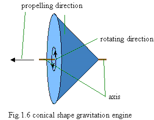
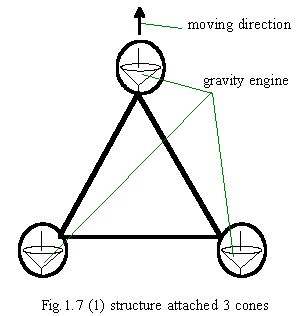
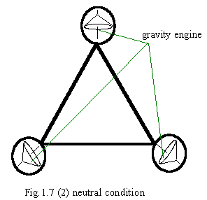
This has a one of perfect shape as basic structure of gravitation propelling engine. Changing propelling direction is only varying the angle of rotating axis. Fig.1.7 is industrial structure which attached least 3 cones to control direction and propelling power.
- Hint1 ; Ring or Doughnut
- Hint2 ; The structure of fig.1.5

 1.8 Gravitation propelling engine with ring structure
 Return to sub menu
 Return to home page
 redsky@graveng.jp